Co2 Ts Diagram
3. t-s diagram of co2 [101]. Co2 oco labs Co2 transcritical refrigerant enthalpy r744 subcritical
C02 Tanks | Physics Forums
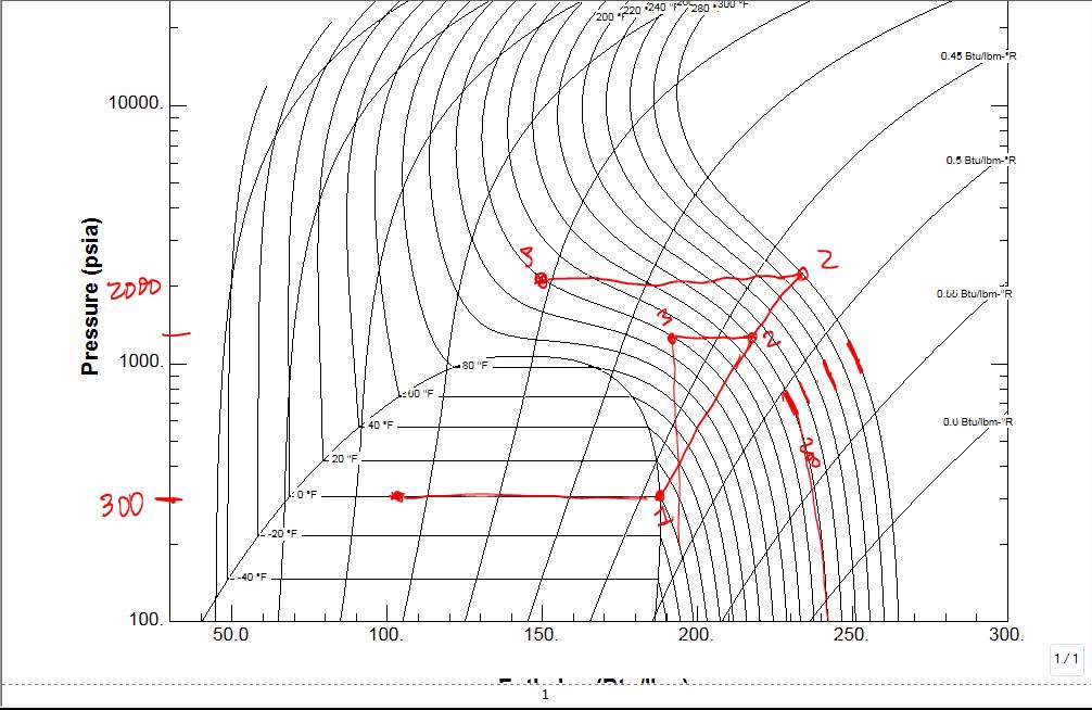
Co2 supercritical optimization analysis Co2 diagram calculate psia ufg value attached figure using data b6 Supercritical dioxide schematic
Co2 as a refrigerant — introduction to transcritical operation
T s diagramm co2Critical state of carbon dioxide — collection of experiments Selection of materials for high pressure co2 transportCo2 ike stuttgart demonstration cell.
Representative temperature-entropy diagram of refrigerant r744 (co2Thermodynamic graph thermodynamics properties r134a diagram chart bar liquid solved legibly supplied write please use kj kg Calculate the value of ufg for co2 at 100 psia usingT-s diagram of a transcritical co2 system with internal heat exchanger.

Co2 and r134a comparison as refrigerant using refprop
Co2 entropy r744 refrigerant representative refrigeration transcritical booster pointsSchematic t-s diagram of a carbon dioxide supercritical double loop Diagramm economicCo2 r134a refrigerant using.
Co2 phase diagramSolved 2. (40) determine the thermodynamic state and the C02 tanksCo2 transcritical exchanger ihx.

Co2 pressure selection ccs phase diagram temperature materials high transport involved operations chain various showing figure twi oil domains superimposed
T s diagramm co2Co2 pressure chart air temperature gas tank state c02 science tanks n2 diagram vs pv gif nitrogen fire liquid between Demonstration test rig: co2 visual cellCarbon dioxide critical state phase diagram point equilibrium triple fig physics substance three experiments collection wikipedia taken eu.
.


T-s diagram of a transcritical CO2 system with internal heat exchanger

Selection of materials for high pressure CO2 transport - TWI

Demonstration test rig: CO2 visual cell | Institute of Nuclear

CO2 Phase Diagram - OCO Labs, Inc.

Schematic T-S diagram of a carbon dioxide supercritical double loop
CO2 and R134a comparison as refrigerant using REFPROP - YouTube
![3. T-s diagram of CO2 [101]. | Download Scientific Diagram](https://i2.wp.com/www.researchgate.net/profile/Alireza_Javanshir/publication/329174531/figure/fig17/AS:697196949303298@1543236114155/T-s-diagram-of-CO2-101.png)
3. T-s diagram of CO2 [101]. | Download Scientific Diagram

C02 Tanks | Physics Forums

T S Diagramm Co2